The Video Streaming System
Being the first attempt to document the programs Gonzales and ImageReader for fast video streaming, including tips for use and installation reports
By Enrico Segre
Weizmann Institute of Science
Oct 27, 2014
1 Generalities
This manual references the construction and documents the use of the fast video hard disk recording systems built for Ehud Ahissar’s group, mostly from the software point of view. There are at the moment of writing four such systems, with small differences among them. There have been continued upgrades to the software which I developed, with a loose versioning notation. At this moment, the topmost versions of the two relevant application programs are the video stream-to-disk application
Gonzales10.3, and its companion movie reader/editor
ImageReader9.3, residing in directory
Gatto10. The numbers are supposed to change incrementally at new releases. Usually a file
CHANGES in the directory briefly documents the new features and issues. (Ad nauseam historical information is reproduced here in Appendix
B↓).
The general user of the systems will be probably interested only in the contents of Chapter
3↓. The rest of this manual covers more technical issues, such as design choices, building and installation of the systems, which need to be documented and referenced somewhere.
1.2 The name
The names of the two main user programs, Gonzales and ImageReader, are because Udi Fonio did not come up in due time with better ones. The contest is also open for nice icons.
1.3 Design Choice
The systems were conceived in the first place in order to have high-speed Digital Video Recording (DVR) installations, with the option of continuous modifications and adaptation to emerging experimental needs. In-house development was preferred to acquiring a turn-key commercial solution, for the perspective of openness of programming and for a system cost which was anticipated to be significantly cheaper. The long development required by system #
2.1.1↓ (months/man) perhaps smoothed the latter point, but the subsequent small effort (days/man) in duplicating to systems #
2.1.1↓ and #
2.1.1↓ completely justified it.
The systems were developed on a desktop-pc platform. Several advantages and a few disadvantages of the choice can be enumerated, but in truth no alternative platform (e.g. a real time target) was considered. A desktop pc OS allows software development already on the target machine, considerably shortening testing cycles; allows integration with whatever other user productivity software; gives the advantage of an immense user and resource basis to look at in case of problems, and so on. On the other side, precise task scheduling is difficult and accurate timing nearly impossible, requiring a lot of programming attention to keep jitter under acceptable constraints. The target requirements for the DVR were zero frame loss and nearly millisecond-accurate timestamping and trigger responsiveness, and it seems that they are met in most operating conditions. Additionally, continuous operation and storage capability for several hours were sought.
The current implementation met this requirements, thanks to the choice of suitable hardware and software, stock and custom, as described in the following.
Labview was chosen as a programming framework for its intrinsic multithreaded parallelism, huge user and resource base, and wealth of resources for building advanced GUIs.
Two topmost user applications were developed, separating the tasks of a) grabbing and recording high speed movies (
Gonzales, see below Section
3.1↓), b) reviewing and editing the saved movie streams (
ImageReader, see below Section
3.2↓).
The principle of operation of the system is to have a fast digital video camera, without internal memory, streaming continuously its images to the framegrabber inside the computer. The incoming images are stored in computer memory in a large circular ringbuffer, in order to mitigate system latency. Currently a hardwired ringbuffer of size equal to 400 images is used, as the number provided a good compromise of performance, tolerance to latency and memory footprint in typical use conditions. As permitted by processing power, thread priorities and access limitations, images within the incoming stream are periodically inspected and subjected to light image processing, for instance in order to detect intensity differences in selected hotspots, or to insert intrusive timestamps. When writing to disk is activated (either by user command or caused by some electrical trigger signal, or after the detection of some image feature in the incoming stream), images from the ringbuffer are written to the disk system in a streamfile. The highest priority is given to the streaming process in order to have a lossless recording to the disk; since the application lives in userspace of a desktop OS, absolute certainty and prevention of disruptions by other OS tasks can’t be guaranteed; it is however in practice achieved.
The target image rate for which the system have been designed is 1.28Mpixel images at 500fps, or 600kpixel at 1000fps, 1 byte per pixel. Given the data bandwidth required, no data compression is even attempted; the raw data is dumped to a huge streamfile with as little formatting and manipulation possible. A custom file format has been devised, which is documented in Section
A↓. This format deviates by necessity, design and choice from common media file formats, and a companion reading application has been built. Otherwise, a programmer is also able to access the streamfile content using the API description provided.
The hard disk system chosen exceeds by some margin the writing throughput required for full size, full speed recording of a single stream at a time. The performance is guaranteed for writing at least in the initial part of the disk storage, for essentially unfragmented files, while no other disk operation is taking part. For that reason, it is recommended to free the hard disk system periodically, and to avoid to use it as a permanent data storage. The disk systems have been designed with a capacity sufficient for storing a few hours of recording. The performance of the disk system in reading back has not been assessed; while there has been no thought of displaying back the movie at the same speed it was shot, a good reading performance would be of concern for operation of analysis of the movie or format conversion. In such case, though, the computational cost of the involved operation may be more determinant than the readout time itself.
The video streaming application and the movie reader/editing application have been deliberately separated, having in mind that the two operations are never supposed to take part simultaneously. Their GUIs could have been integrated, but for modularity of development it has been chosen not to.
The platforms chosen have sufficient computational power to allow parallel run of other user applications, such as the experimental trial software
BEst (Eldad Assa) on system #
2.1.1↓. Applications with simultaneous slower grabbing from an additional range camera have also been tried.
2 Installation
Here is a list of hardware and software components required for the complete setup of the video system, with some notes about where to get them from, and about experiences in building the four systems to date.
2.1 Hardware
2.1.1 Server platform
Four systems have been built so far:
-
ahissar-pc55 (“Udi’s”, “room 69”), building (assembling and setup at WIS) started 6/5/2009;
-
ahissar-pc66 (“behavioral”, “Inbar’s”), built about 9-10/2010, as an exact copy of #2.1.1↑
-
OPTOWHISKER (“Tess’”), building started 23/12/2012.
-
MAMTAK (“Noy’s”), building started 19/12/2013.
The first two use a server-class Tyan Tempest 5400PW S5397 motherboard; the third one a Supermicro. The fourth an i7-4930 @3.4,4GHz motherboard, with 32GB RAM.
In general warranty on hardware components was given for three years, which implies that system #
2.1.1↑ becomes difficult to maintain. In addition, the commercial life and availability of computer components is nowadays short, and hinders the long-term serviceability of the systems.
We are using on the four setups an Optronis CL600x2, which is a 500fps, 1.3Mp, 40%QE full CameraLink CMOS camera. The four cameras were purchased at subsequent times and have different versions of firmware installed. Notably, the camera used in setup #
2.1.1↑ has a firmware (already upgraded at least once in the past) which is buggy in its feature of framestamping.
In initial stages of the development a Basler A504k was also considered, then dismissed because of lower sensitivity (~10%QE peak). Gonzales once could use either the CL600x2 or the A504k, and has been since then incrementally developed still including the full set of commands required to drive the latter in its various modes, but the functionality is untested since long. If it would be needed to use a recent version Gonzales with the Basler A504k, a complete reassessment would be needed, as plug-in compatibility of the old camera can’t be taken anymore for granted.
Different camera models differ greatly in their set of serial control commands, and hence new software has to be developed for each different model, should a different new camera be considered. In practice, this would amount to rewrite or augment a small part of the code of Gonzales to support new camera modes.
The maximal number of frames per second (fps) which the camera can deliver is an arithmetic function of the width and height of the image, of the pixel clock and of the number of taps of readout (essentially, but not exactly, fps≃(clock*taps) ⁄ (width*height)). The details are documented in the camera manuals. The maximal exposure time at a given fps is a few microseconds less than 1 ⁄ fps.
2.1.3 Framegrabber
After an initial attempt in
2.1.1↑ with the older framegrabber National Instruments NI-1429e (PCIe x4) which was not up to the task, we adopted for the first three systems the Bitflow Karbon-CL-full (PCIe x8) (KBN-PCE-CL2-F). This framegrabber was, as of end 2012, announced as going end-of-line, but the KBN-PCE-CL4-F is available instead, and was used in
2.1.1↑. All versions of
Gonzales require now the presence of the Karbon, and won’t work with another framegrabber without modifications of some extent.
The framegrabber has to be placed into a true x8 PCIe slot to deliver full performance. In the first two systems, one of the PCIe slots is physically large (x4), but truly connected as x1 only.
On the first two systems, the framegrabber “prevents the system entering sleep mode” according to the OS.
On system #
2.1.1↑, it happens occasionally that the framegrabber is not recognized by the system at cold boot. In such cases, turning off the computer for a few minutes and then on may solve the problem. In the past, we went even as far as extracting physically the card and reinserting it, but that is probably unnecessary.
2.1.4 Disk array and RAID controller
In all four systems, an array of 8 disks attached to a dedicated LSI PCIe controller was used. On the first two systems the individual disks are of 1TB (SATA, I think), on the third of 2TB.
System #
2.1.1↑ originally used a different RAID controller (LSI Logic MegaRAID SAS 84016E and an array of 9 disks), which was underperforming AND hogging the system buses to the point of slowing down the system clock (which caused very puzzling timing results). That controller has been since then replaced with a LSI MegaRAID SAS 9260-8i).
System #
2.1.1↑ has suffered from failure of several of the original hard disks (which were lower grade 700GB units). In summer 2012 the whole set of disks has been replaced.
System #
2.1.1↑ is supplemented by a NI-6501 24port digital i/o USB card used for triggering. The program
Gonzales knows how to make use of National Instruments with DI/O ports if found on the system.
2.2 Software
The following is a list of components to be cared for, installed and configured.
The choice is unfortunately limited to Windows for availability of Labview vision development modules.
Systems #
2.1.1↑ and #
2.1.1↑ run on windows XP32. The choice was dictated by compatibility problems with the rest of the software available at the time of the assembling of the system (XP64 was tried on system #
2.1.1↑ and Windows7 64bit on system #
2.1.1↑). Systems #
2.1.1↑ and
2.1.1↑ run Windows7 64bit.
2.2.2 RAID setup
32bit OSs do not support volumes other than formatted as MBR and larger than 2TB, hence logical RAIDing of MBR subvolumes has to be done by the OS (Manage storage devices/create dynamical disks).
The four systems have been provided with a configuration tool by LSI, functional save some quirks. (The tool requires credentials; current ones are
Administrator/barrel05/ on systems #
2.1.1↑ and #
2.1.1↑,
Admin// on #
2.1.1↑).
-
system #2.1.1↑ and #2.1.1↑ have been configured as 4 logical volumes of 2 disks each, independent volumes at controller level.
-
system #2.1.1↑ has been configured as a single logical volume including all 8 disks at controller level.
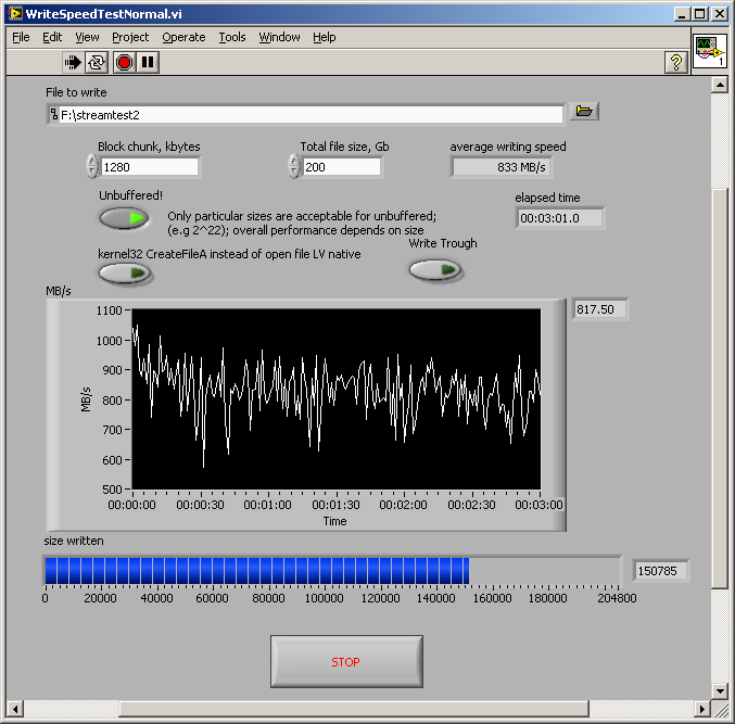
The writing throughput of all systems has been checked with the tool WriteSpeedTestNormal described in Section
3.3.1↓. Sustained writing speed in excess of 750MB/s are desirable in order to allow enough throughput for full speed, full size grabbing (625MB/s). The need for a somehow higher writing speed is probably due to the fact that DMA transfer to and from memory, and PCIe bus arbitrage limit the parallelism of grabbing and dumping data to the disk controller; some part of the transfer may need exclusive hold of the data buses.
The best configuration parameters for the RAIDed disks appear to be: Stripe length 64kB, Write Policy Always Write Back. Setting Write Policy to Write trough negatively affects the throughput. The effect of the setting I/O policy (Cached or Direct I/O) seems unimportant for the purpose. With those, all four systems seem capable of sustained average throughputs of the order of 850-900MB/s.
The effect of RAID parameters related to the Read policy has not been assessed, but could be relevant for optimal performance of ImageReader in scanning movies for activity or exporting movies.
2.2.3 Framegrabber driver and SDK
Probably the driver has to be installed before the installation of the card for smooth system recognition.
We did not buy the full SDK license, hence we do not have an authorization code to provide to the installer, and only a part of the toolkit gets copied. In particular, we miss the functionality for changing programmatically some framegrabber modes, and we have to resort to the tiny prebuilt tools for that.
Useful tiny tools: for the user, SysEx (checks that the Bitflow framegrabber is recognized, chooses the camera configuration file and sets bus priorities); CiView (previews the camera image, if all is set up and camera is started correctly). There is also CamEdit for creating camera configuration files (for advanced users only).
2.2.4 Camera configuration files
I have created (with the tool
CamEdit provided by the Karbon SDK) a few camera configuration files for the common image formats used. These files need to be copied in the directory
<SDKdir>\R64\Config, where
<SDKdir> may be e.g.
C:\Bitflow\SDK 5.60\ or such depending on installation. We need different files for various formats because, since we don’t have the license for the part of the SDK allowing to change the resolution and tap mode of the image grabbed by the Karbon, I use the trick of swapping configuration file references in the Windows Registry (see
http://www.bitflow.us/Forum/viewtopic.php?p=1034).
Additional configuration files could be built with
CamEdit, to allow for different combinations of image sizes and shooting speed, keeping in mind the design limitation mentioned in Section
1.3↑. It has additionally to be kept in mind that only particular image widths are admissible by the combination of Karbon SDK + Labview (see
http://www.bitflow.us/Forum/viewtopic.php?t=398). Namely, the width of the image has to be a common multiple of 64 and the number of taps (8 or 10).
Systems #
2.1.1↑ and #
2.1.1↑ have installed a 32bit version of LV2009 (f2, if I don’t err). On system #
2.1.1↑ we tried LV2010 on 32 and 64bit Windows XP, but the choice (together with SDK 5.20 or 5.30) proved unworkable because of an obscure bug causing LV crash when particular CameraLink serial commands were sent, preventing in practice the operation the camera (see
http://www.bitflow.us/Forum/viewtopic.php?t=400).
On system #
2.1.1↑ we’re going on with LV2012 64bit, and on
2.1.1↑ with LV2013 64bit. The installers of the 64bit versions of LV and VDM are not provided by the standard DVD set, and have to be requested specially or downloaded from
http://www.ni.com/downloads/. The disk of the Device Drivers included in the set, instead, is ok (though 32bit?)
It is important to install either 32bits or 64bits versions of all software (OS, drivers, LV) because interoperability of 32/64bit components on a 64 bit system if not guaranteed, if ever conceivable (perhaps possible with the latest versions?).
2.2.6 Framegrabber LV layer
2.2.7 Camera control software
Optronis provides a small program called CamSetup, to change/report camera settings via serial-on-cameralink commands. Though the useful part of the functionality of this program is duplicated in Gonzales, the tool may be handy for independent testing. Note: earlier versions of CamSetup, installed on the first two systems, don’t support 10tap modes.
2.2.8 Application programs
Gonzales, ImageReader, coming along with their ancillary Labview library files (llb), provided by me. My strong attitude is to provide a single version of these programs for all systems, and to maintain only the very latest version of the two programs. The aim is therefore to leave as many features inside the programs as possibly needed in all use scenarios when creating new versions, removing unused features only if really obsoleted.
The past experience has been that unfortunately, due to the software and hardware differences between the four platforms, porting a new version of the programs developed on one system to the other two is never just a matter of copying some file; additional troubleshooting and adaptations have always been necessary. I’m striving each time to produce more portable and auto-adapting versions, to reduce this cost and dependence on my exclusive expertise.
Developing Gonzales at the present state is possible only in presence of the grabbing hardware, i.e. on one of the four systems themselves, while it is possible to develop ImageReader on a different computer with the necessary components of Labview installed.
2.2.9 AVI codecs
Movies or excerpts from them can be exported from ImageReader in either native stream format, or uncompressed AVI, or AVI various compressed by mean of various codecs. The codecs seen by the Labview program ImageReader are those installed systemwise, hence if some odd ones are desired, they have to be taken care of.
2.2.10 Goodies and Ancillaries
A few other files are usually included in the relevant (the latest) GattoN directory, containing the latest version of my programs. These may include small test programs like WriteSpeedTestNormal, UDPReceiver2, which may be useful for troubleshooting, or sample matlab scripts.
3 Applications: user manual
3.1 Gonzales
The program runs on opening, and tries to connect immediately with a running camera. The program reads a configuration file, if that is present, containing all the settings saved automatically at the end of the previous run. If the camera is turned off, or if there is any other hardware or setup problem, the program may hang for several seconds and be unresponsive.
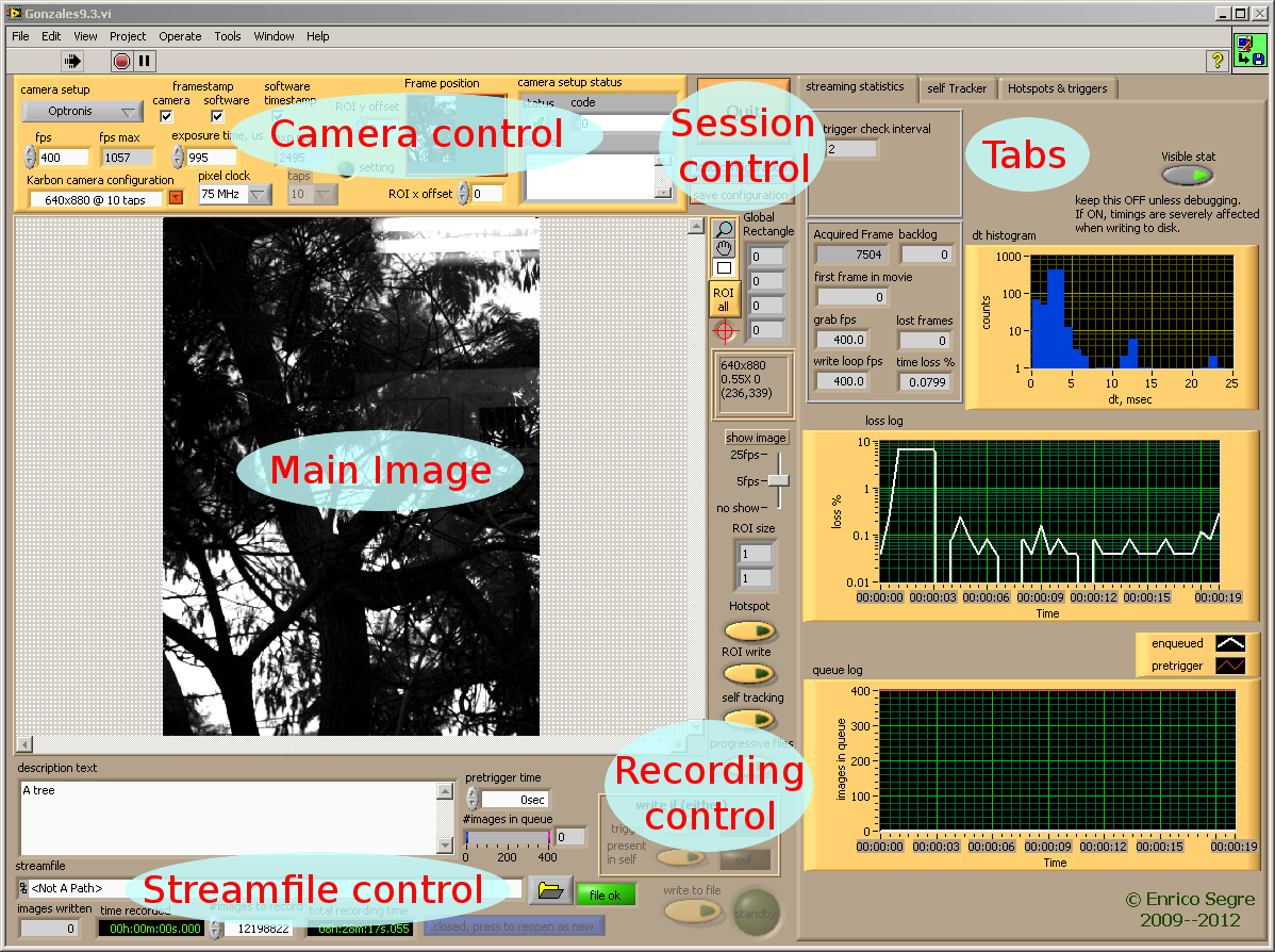
The program opens with a front panel window depicted below, where the various controls and indicators are broadly grouped according to their function. The following sections describe each group.
3.1.1 Main image tools and information
The program shows in its larger inset window the image acquired by the camera (if it is turned on, if there is enough illumination, if parameters are correct). Since there would be no point in trying to show every image coming from a fast camera (the eye would not appreciate, and the computational load would be prohibitive), the display is refreshed as specified by the
↓Show Image slider. Normally
5fps is a reasonable compromise providing enough feedback about what is happening under the camera without spoiling the exactness of software timing; in normal circumstances even
25fps is affordable. For testing purposes (e.g. on former systems on which screen drawing was very CPU intensive, and interfered with video streaming), the display can also be suppressed (position “
No Show”). In such case, clicking on the image still refreshes it.
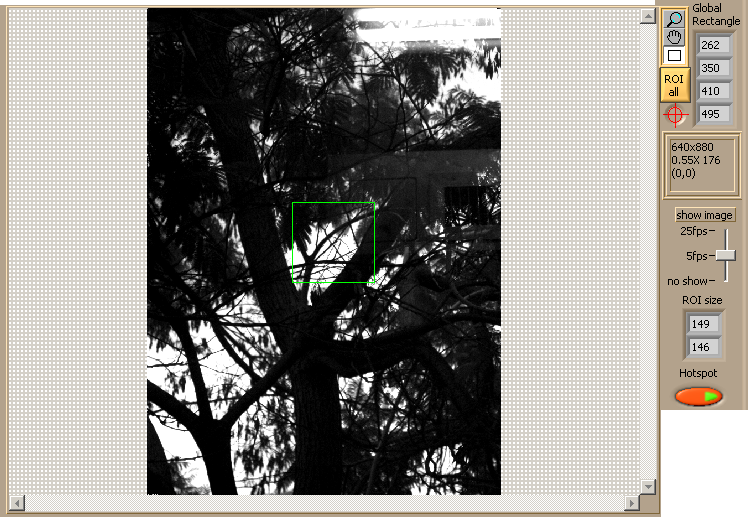
The main image can be zoomed in or out (select the
 lupe↓
lupe↓ tool at the upper right corner of the image), panned (select the
 hand↓
hand↓), or rectangular
Regions
Of
Interest (
↓ROI) can be drawn (select the
 rectangle↓
). Multiple ROIs can be drawn holding Control; ROIs can be dragged around and adjusted by their corner handles, and a right-click menu allows to clear them selectively.
There are few different uses of the ROIs. As functionalities were added along time when new requests emerged, some of these functionalities may seem odd nowadays, or don’t exactly harmonize one with the other. Wherever possible, effort has been made in order to preserve all older functions when adding new ones, though it may be that bugs slipped trough the cracks. For some of them only one ROI (the first defined) makes sense, other functions are designed to support multiple ROIs. The functions are described below in the relevant subsections.
The button
 ↓ROI all
 creates a single ROI enclosing the whole image.
Below it, the recessed button with a
 ↓crosshair
 symbol toggles the drawing of a red crosshair in the center of the image. This may be of no use nowadays, it was an aid in pointing and tracking in earlier versions.
Below these controls, an anonymous frame displays: the current image size, the current zoom factor, the intensity value of the pixel under the cursor and its coordinates, when the mouse is hovered over the image.
The indicator
↓ROI size reports the size in pixels of the first ROI currently defined, while
↓Global Rectangle gives the coordinates of the opposite corners of the rectangle enclosing all ROIs.
Hotspot↓ enables the computation of differences within ROIs, and its use for generating trigger, as explained in section
3.1.8↓.
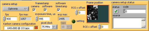
3.1.2 Camera control
Above the main image, inside an orange beveled frame. This frame groups several controls changing the mode of operation of the camera, and some checkboxes determining the kind of invasive framestamp added to each picture. Two of the framestamps options are generating by the program, rather than being modes of operation of the camera itself, but pertain to the same logical group. As per each individual control and indicator:
camera setup↓ selects between
Optronis (our current only option in all systems),
Basler (if still works across versions) and
no serial command. The latter is a fallback option for eventual unknown cameras, or problems in sending serial commands to the camera. The setting also determines which of the other controls of the frame are visible and enabled, as the two cameras don’t support perfectly equivalent commands and modes. There is no point in using
Basler in a setup with the Optronis; camera commands are different and wont have any predictable effect.
Karbon camera configuration↓ is a pulldown menu which allows to choose among the available camera configuration files (see Section
2.2.4↑). When one is chosen, the disabled control
↓taps shows the pertinent number of readout taps, and the indicator
fps max↓ the maximal number of frames per second which the camera can deliver at that image format, as communicated by the camera.
fps↓ The actual speed of take can be set with the control
fps, with resolution of 1 fps. The value entered is clipped to the maximum possible. The minimal value for the Optronis is 20 fps.
exposure time us, exp max↓ The exposure time in
μs is set by
exposure time us↓, and limited by the value communicated by the camera and indicated in
exp max, slightly smaller than 1/fps (due to a dead time before readout). If
fps is changed,
exp max changes, and
exposure time us is reduced automatically if needed. In general usage, an exposure time as long as possible allows to collect more light, whereas it may be desirable to reduce it to reduce motion blur.
pixel clock↓ refers to the camera readout speed. The Optronis allows to choose between 66, 75 and 85MHz, and the setting affects the maximal fps attainable. A higher readout clock may increase the occurrence of salt-and-pepper noise, whereas it seemed, mostly on system #
2.1.1↑, that a lower pixel clock increased the chances of loss of sync of the frame.
Camera configurations which dictate a frame size smaller than the sensor size (
1280 × 1024 for Basler A504k and Optronis CL600x2) can be chosen with
Karbon camera configuration. In that case, the user can choose which part of the image collected by the sensor to use. The position of the part of the total area to be imaged is controlled by
ROI x offset↓ and
ROI y offset↓, and the location of the subpart of the image used is shown in the small
Frame position↓ frame. The small image is updated infrequently. [It is not possible to display also the rest of the image: doing that would require to switch the camera periodically to full frame, reinitializing the framegrabber, which is prohibitive]. The small image can also be dragged within the frame in order to change its location. Image update is slow, though, which hinders the interactivity of the control.
camera framestamp↓ if checked, turns on a feature of the camera, which replaces the intensity values of a few pixels in one corner of the image with status information including a 16 bit frame counter, and for the Basler, the coordinates of the subframe if the camera is delivering a subframe. The Basler camera uses the last 10 pixels of the last image line; the Optronis the first 2 pixels of the first line. See Appendix
A↓.
software framestamp↓ if checked,
Gonzales replaces the first 20 pixels of the last line with an image counter and other information (see Appendix
A↓). Comparing this counter information (which depends on the software performance) in the images of a recorded movie with the previous counter can reveal lost frames.
software timestamp↓ if checked,
Gonzales replaces the first 8 pixels of the first line with a millisecond absolute timestamp (see Appendix
A↓). The time is read from the OS clock, hence may suffer of jitter, which could be analyzed statistically.
camera setup status↓ is an indicator which displays specific program errors in case of problems in the communication with the camera. In normal operation it should display nothing, while in case of error the message may not be that useful to the end user. In short, a debugging indicator which occupies perhaps too much screen space.
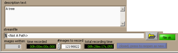
3.1.3 Streamfile control
Below and by the lower right corner of the main image. The group includes controls relating to the movie file.
streamfile↓ is the path to the file. It is self understood that it should point to some location on the logical volume built on the RAID array. The path is emptied every time that a camera parameter is changed, to prevent any attempt of dumping to the same file image content taken with different parameters. To maximize responsiveness, the file is created and opened as soon as the path is chosen or written in. An initial header is written, in which the total frame count is set to 0. This header is then later updated with the total number of frames in the movie, when the file is closed. If another file is chosen before anything is recorded, the first file is automatically erased. If opening or writing fail for any reason (e.g., non-existing path), the led at the right of the control changes to “
Error”, instead of “
file ok”.
open file button↓ Though not so intuitive for the casual user, it is possible to close the file, releasing its lock and allowing the file to be read by another program, e.g.
ImageReader. The file can then be reopened to resume writing, appending content. I would not recommend working this way because it may lead to confusion (ending in writing and reading different files at the same time and thus degrading throughput), but the feature is there.
description text↓ is free text written in the header of the file (on write, it is truncated to 458 characters). The text can be modified as long as the file is open, because the header gets rewritten at the end of the recording.
images written↓ is a counter of images recorded.
time recorded↓ reports the recording time (assuming no frame loss, i.e. reporting fps*images written). To avoid unnecessary screen activity, the indicator is updated periodically every 10ms and not for every frame written.
#images to record↓ In order to prevent the recording to go on forever, a maximal number of frames can be specified. When the filename changes and a new streamfile is opened, the default is to keep the previous number if
progressive files↓ is on (see below section
3.1.4↓), otherwise the number is set to the maximum, computed according to the disk space available.
total recording time↓ reports the expected duration of the recording (assuming no frame loss), based on the current values of
fps and
#images to record.
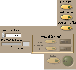
3.1.4 Recording control
This group comprises controls which, loosely said, determine how and when the streamfile is written.
Write to file↓ This is the button which the user presses on the GUI to initiate recording (i.e., to cause the images that are
continuously grabbed to be
actually written to the streamfile). The button is disabled if no streamfile path has been selected, if the file is momentarily closed, if there is a file error, etc. The writing status is evidenced by the red led at its right. Writing can be suspended by pressing again on the button.
writing led↓ This led changes from
standby (dark green) to
REC when recording is actually taking place. The led is greyed out when recording is impossible, for instance when no
streamfile↓ has been defined and opened.
Writing can also be caused to turn on and off automatically, in which case the button toggles by itself depending on what is happening. In addition, writing stops automatically when approximately
#images to record↓ have been written. [Approximately, because the checking mechanism involves different threads which are by implementation asynchronous]. The following controls determine the automatism:
write if trigger↓ writing turns and stays on as long as a TTL trigger is 1 on the digital input specified in the Hotspots and Triggers tab (see below section
3.1.8↓)
write if present in self↓ is only active if
self tracking↓ is turned on. The yellow led at its right shows when the “self” condition is on. [CHECK--maybe if
self tracking is off, it simply dumbs down to write-if-difference-in-ROI, and is still enabled]
If any of the two controls above is turned on, the button Write to file is disabled, intending by that that the starting or stopping the recording is delegated to the triggers and no more an user choice.
pretrigger time↓ determines how many images preceding the write command are written to the disk, and how many images
before the stop command are omitted from the end of the stream. [The two numbers should perhaps be separated, and posttrigger should also be allowed, but since interest for the feature after the initial request seemed low, I omitted the implementation]. Pretriggering is made possible by the fact that, by design, the images which are continuously grabbed are stored in a ringbuffer, while reference to them together with a flag signaling if they are to be written is to the disk is stored in a queue; a separate thread cares for dequeuing and actual writing. It is sufficient to choose to write an image from the ringbuffer a number of positions behind the last one in queue, when the writing flag appears in the element dequeued, in order to achieve pretrigger recording. The number of images written, preceding the trigger event, is simply
tpretrigger/fps. The exactness of the feature depends on the responsiveness of an event checking thread, and is therefore subjected to OS timing jitter. The maximum pretrigger time is
Nring ⁄ fps, where
Nring = 400 hardwired in the program.
#images in queue↓ Related to the writing process, the indicator
#images in queue reports the number images which have been grabbed but not yet been written to the disk, and wait in a queue. In normal conditions, this indicator should show an empty queue, or a queue which fills in small bursts which are rapidly disposed of. Abnormal conditions like high system load, disk failures or the like cause the queue to fill rapidly as writing stays behind; images older than the queue size are lost as the ringbuffer is overwritten circularly. If a pretrigger time larger than zero is used, the effective headroom decreases, because it is both required that the image is still in the ringbuffer and that the relative reference, including the write flag is still in the queue. The queue size is currently 400 elements long as much as the ringbuffer size is, but that is in fact a limitation which could be very easily lifted, at insignificant memory cost.
progressive files↓ when on, files are automatically “sequenced”. That means that whenever recording stops (either because the user presses the button or automatically), a new file is created and opened; if the name ended with non-numeric characters then
_1 is appended to the name, and if the name ends with a number, that number is incremented.
ImageReader also refers to files named according to this scheme as “sequenced”. When off, images are appended to the opened streamfile, as long as it is not changed. Than means, that if writing goes on and off and then on again, discontinuous pieces of movie will be consecutive in the streamfile (perhaps discernible by frame or timestamps). This may be wanted or not, the choice is to the user. Closing files and creating new may have a small (tens of milliseconds) OS overhead, so perhaps
progressive files off would be preferable if very short off intervals are to be expected. I doubt that the case had practical relevance so far, though.
ROI write↓ only the portion of the image enclosed by the first ROI is written to the file.
self tracking↓ determines if Self Tracking is activated. The functionality is described below in section
3.1.7↓. The button is relevant to streaming too, because if self tracking is on:
-
the condition write if present in self can be activated;
-
if ROI write is on, the (single) ROI of the main image is adjusted dynamically, following the centroid of the detected blob and preserving its size. The intended effect is that the movie records a subimage, which tracks a single moving object detected in the larger frame. The limitation is that blob analysis needs some tens of milliseconds to be computed, hence the ROI position can be updated only every several frames when acquiring at high speed, and the resulting effect is rather jerky.
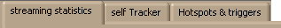
A wealth of additional diagnostic information, as well as configuration which does not need to be constantly observed by the user, has been organized in tabbed pages in order to economize screen space. Tabs are switched to by clicking on their labels on top of the page.
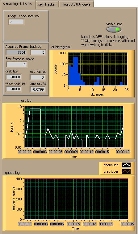
3.1.6 the Streaming statistics tab
This tab shows a lot of statistic information about the enqueuing of images grabbed and waiting to be written, which is important for debugging and troubleshooting anomalous conditions, but less useful for the normal use. The indicators in this tab cause a lot of video activity, which increases the jitter in all timings. Because of that, there is a switch
↓Visible stat in the upper right corner, with a caption encouraging the user to keep it off. In the off position, all indicators but
first frame in movie and
lost frames (if supported) are made invisible. [In fact, having this tab open with
Visible stat off is the position causing the least video activity among the three tab options].
The meaning of the indicators is the following:
↓trigger check interval reports the time in milliseconds needed for one iteration of the loop, in a separate thread, which scans the DAQ inputs and checks for changes in the triggers.
↓Acquired frame the progressive number of the frame grabbed, starting from 0 at reinitialization. Should increase continuously at rate
fps, as long as the camera is on.
↓backlog number of images which have already been grabbed but not yet written. Should be 0 or very small.
↓first frame in movie the frame number displayed by
Acquired frame at the moment the recording is started.
↓grab fps an estimate of the fps based on the average timing of iterations of the grabbing loop. Should coincide with the camera
fps (section
3.1.2↑), but can fluctuate around it especially if the system is loaded. A value significantly lower than
fps means that the computer is not able of grabbing all of the images delivered by the camera, or that the camera is not behaving as expected.
↓write loop fps an estimate of the fps based on the average timing of iterations of the write-to-disk loop. Should coincide with the camera
fps (section
3.1.2↑) and with the
grab fps, but can fluctuate around them especially if the system is loaded. A value significantly lower than
fps means, if recording is active, that the computer is not able to write the images to the disk as fast as they come in, and will be associated most likely with a filled queue and overwritten ringbuffer (described above in section
3.1.4↑); if recording is off, it may indicate some odder problem.
↓lost frames indicates the number of frames produced by the camera since the last reinitialization, which the computer did
not pass to the writing loop (either because problems in grabbing or in writing) and which were therefore lost. The count is possible only if
camera framestamp is checked, since there is information about the number of frames from both sources. The number should be 0 as long as the process is regular. If the image queue fills up, the
lost frames count will increase in multiples of the ringbuffer size, i.e. 400. If the camera “looses sync”, the number will be meaningless, because the pixels which should contain the camera framestamp will not be in the right position on the received image. The counter provided by the camera is only a 16 bit one, so in principle the number of lost frames wraps around 65536.
↓time loss % an estimate of the percentage of lost images, based on the comparison between the average timing of the iterations of the write loop and
1 ⁄ fps. Never an exact value due to OS timing jitter, it should normally be around 0% (even negative). Values below 1% are the normal condition. The computation is based on an average of the last 1000 iterations, and can therefore be wrong for the first few seconds after
fps is changed.
dt histogram↓ a histogram of the distribution of timings of the last 1000 iterations of the writing loop. It should normally be peaked around
1 ⁄ fps, taking into account that the timing has 1ms granularity. The delay-tolerant design of the loop allows delays to accumulate in some iterations of the loop, which are then compensated by a faster successive iteration. This results in wider peaks of the histogram, with the appearance of both longer and shorter sampled values of the timing. The histogram in particular widens under heavier load, e.g. increased screen activity.
loss log↓ charted history of the
time loss %
queue log↓ charted history of
#images in queue described above in section
3.1.4↑.
3.1.7 the Self Tracker tab
Self-tracking was a feature introduced tentatively in earlier versions of Gonzales, which as of itself has probably not been exploited much in experimental use. The feature has been preserved until now, and some parts of it are still relevant, hence they are described here.
Self-tracking implies that a reference “background” image
↓ is taken; then, as often as possible the grabbed image is compared to the reference, and if a significant difference is found, the coordinates of the centroid of the detected object are used further. The feature can be meaningful if there is a single object to be tracked within a larger arena imaged; it is much less if there are many objects, or if the object is complex, not completely imaged, or with a size comparable to the area of the image.
For self-tracking, the absolute difference between the most recent grabbed image and the reference is computed; the result is then binarized setting to 1 all pixels with intensity between two thresholds, and this result is morphologically eroded in order to remove isolated pixels. On a single thread, the image processing task may require times of the order of 10÷20ms (depending on image size and content), and hence, at high fps, it is repeated whenever possible and not on each image grabbed. The controls in the tab relate to this process. In detail:
selftracking delay↓ reports the time in ms needed for the last iteration of the image processing loop
take as reference↓ stores the last image grabbed as reference background. This image is also used as reference for the Hotspots functionalities (section
3.1.8↓).
auto update ref↓ if on, the reference image is updated periodically. Supposed to be useful for experiments in which the background may occasionally change (objects in the field of view are displaced, illumination changes)
every↓ period of update of the background, if
auto update ref is on
reference image↓ a display of the reference image, once stored. The image can be zoomed in and out with the lupe tool, and has a contextual right button menu (as provided by the standard LV image widget).
thresholded self↓ the binary image resulting from the absolute difference of the grabbed image and the reference, thresholded and eroded. If
self tracking (see section
3.1.4↑) is on, a ROI, as big as the (single) ROI defined in the main image is drawn, and its center is moved so to track the centroid of the white pixels in this image. The same ROI rectangle is also adjusted dynamically in the main image.
Lower threshold↓ the minimal intensity value of the difference image to be treated as white.
Upper threshold↓ the maximal intensity value of the difference image to be treated as white. Usually set to 255.
erosions↓ The number of morphological erosions applied to the difference image. A higher value removes larger objects, but increases the image processing time.
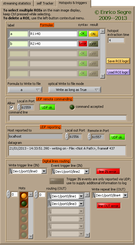
3.1.8 the Hotspots & Triggers tab
A quite dense panel, concentrating various configuration functions. The panel deals with:
-
Detection of activity in the ROIs (the Hotspots↓) defined in the main image, and computation of logic functions involving them (Formulas↓)
-
Configuration of an UDP listener service, allowing other programs on the same computer or on a computer across the network to send commands to Gonzales while it runs (UDP remote commanding↓)
-
Configuration of a service sending event messages to an external logger, potentially listening via UDP (UDP reporting↓)
-
Routing of digital triggers, to which Gonzales reacts or which Gonzales generates, to the available ports of eventual DI/O cards (Digital lines routing↓)
The description of each group follows in the next paragraphs.
One or more rectangular ROIs can be drawn on the main image window. When they are, the the values of the pixels inside them are constantly monitored, and can serve as basis for logic operations, such as sending flagging messages to an external logger when some condition is met, turn on the recording of a movie, change the status of a digital trigger.
For each ROI defined, the content of the ROI is subtracted from the corresponding pixels in the reference image
↓ (see section
3.1.7↑); the average of the absolute value of the difference is referred to as the
R value↓, and displayed numerically as an overlay to the main image.
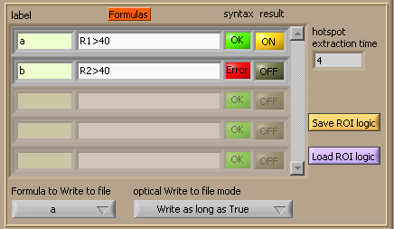
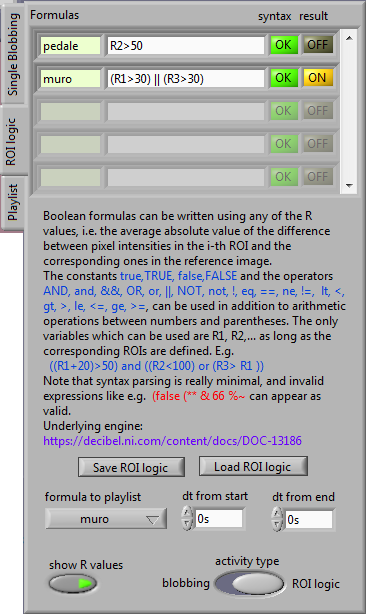
Boolean formulas can then be written using any of the R values, and entered in the cluster array
Formulas↓. The standard Labview Array widget behavior applies; undefined elements are greyed out, elements can be inserted or deleted with right-click menu entries, and so on. Each formula cluster element has four field:
label↓,
formula,
syntax↓ and
result↓.
In the formulas, the constants true,TRUE, false, FALSE and the operators AND, and, &&, OR, or, ||, NOT, not, !, eq, ==, ne, !=, lt, <, gt, >, le, <=, ge, >= can be used, in addition to arithmetic operations between numbers and parentheses; the result of the formula must be logic and not numeric. The only variables which can be used are R1, R2,... as long as the corresponding ROIs are defined. E.g. an expression like ((R1+20)>50) and ((R2<100) or (R3> R1)) is a legal formula. Note that, as with any Labview string entry control, the formula is effectively entered only when the key Enter is pressed, or focus is moved to another control.
A syntactically wrong formula is flagged by the indicator
syntax in the formula cluster becoming red. A formula involving symbols other than the few R active is considered syntactically wrong, and sometimes arithmetic operations have to be surrounded by extra parentheses. Note that syntax parsing is really minimal, and invalid expressions like e.g.
(false (** & 66 %~ can appear as valid. The evaluation is performed by a very simple underlying parsing engine which I found on a technical forum,
https://decibel.ni.com/content/docs/DOC-13186. The engine is nor fast nor sophisticated, but it was the best available.
The formula cluster has an additional input field
label, which can be used as mnemonic, and an indicator of the
result of the evaluation. The Formulas are evaluated as frequently as possible on the last image available, but the evaluation is asynchronous with respect to grabbing. The evaluation of the formulas takes usually a few milliseconds, time which is reported in
hotspot extraction time↓.
For reasons which are more historical than anything, the
Formulas are evaluated only if the
Hotspot↓ button (described in section
3.1.1↑) is turned on. Otherwise, they always evaluate as
false for all practical purposes.
Both the coordinates of all ROIs defined and the formulas can be saved in a plain text file and reloaded, using the
Save ROI logic↓ and
Load ROI logic↓ buttons.
The result of one among the formulas defined can be used to control the recording of movies. The controlling formula is chosen with
Formula to Write to file↓. The action selected by
optical Write to file mode↓ can be either
no action (nothing happens),
Write as long as True, or
Start when becoming True. The action is equivalent to pressing the
Write to file↓ button (section
3.1.4↑). Note that the last two options may cause conflicts with other automatic or triggered ways of starting or stopping the recording.
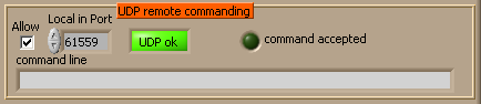
3.1.9.1 UDP commanding
A powerful and potentially disruptive feature of Gonzales since version 10 is that the values of many controls and indicators can be changed by an external program sending a suitable command string to a particular UDP port of the computer running Gonzales. Uses of this feature can be a lot: starting/stopping the recording by command, changing the movie pathname, resetting the background image, changing the image format, and more. The controls which can be commanded at the moment of writing are all those displaying a single numeric value, a string, a logic value, as well as rings and pulldown menus.
In order to change a value,
Gonzales has to receive on the
Local in port↓ an UDP datagram terminated by a newline, with the format
set “control name” value
The name of the control,
control name, is the internal name in Gonzales. In most cases it coincides with the label of the control on the front panel, but sometimes it doesn’t, if for UI clarity the caption of the control has set to something different (e.g.: the control labeled
present in self (section
3.1.4↑) has the internal name
write if self).
Boolean controls can be changed with value equal to True or False (case ignored).
Examples:
set “take as reference” true
set “write to file” TRUE
set “pixel clock” 1
set “ROI y offset” 32
set “streamfile” F:\test1\streamtest_new
Note that parsing of the command is very crude—extra words between set and quotes are ignored, and only the first letter t or f is taken into account for booleans. Hence even this would work:
set ohy ohi “camera framestamp” trumpatrumpatretre
As the controls in Gonzales are too many, I won’t provide here the full list of their current internal names; in case someone needs a specific one, which differs from the displayed label, look it up in the code or ask.
The feature can be quite disruptive if used without criterion, or if a malignous entity sends inconsiderate commands across the network, as no consistency check is done on the values changed and on their sequence. To provide a really minimal level of security, the checkbox
Allow↓ has to be tagged in order to enable the feature. As a matter of fact, even the values of the indicators can be changed with the same mechanism, though
Gonzales will in most cases rewrite these values by itself shortly thereafter.
command line↓ will show the last newline-terminated command received by Gonzales.
command accepted↓ turns and stays green if the last command was syntactically correct [
which does not imply that the value changed is legal]
UDP in status↓ becomes red if the chosen
Local in port is not available, e.g. is it already in use by some other service.
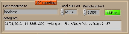
When certain events happen, a timestamped report message is generated and delivered trough UDP. The main use intended with that is to report conditions to an external logger sitting somewhere on the local computer or across the network and listening onto a specific port. In the behavioral setup, BEst includes this functionality. UDP is chosen as protocol because of its simplicity and because of its independence on an actual listener.
Events which are reported are: the start and the stop of a recording; the change of result of a formula (hotspot on or off); the change of state of the trigger line. If the event happens while Gonzales is recording a movie, the current filename and frame number (with some inaccuracy due to the asynchronism of the involved threads) are also reported.
Relevant controls are:
Host reported to↓ the UDP message is directed to a specific receiver on a host [it could be sent in broadcast mode, instead; the change in the program would be trivial]. The address can be given as IP or as hostname. Use
localhost if the message is to be used by a logger (e.g.
Best) on the same computer.
Local out port↓ the UDP port used for sending out the report message. Number between 0 and 65535, taking into account that many ports are already used by default by system services. It can’t coincide with
Local in port↓ used for UDP commanding.
Remote in port↓ the UDP port on which the receiver is listening for messages. If
Host reported to is the same computer on which
Gonzales is run, it can’t coincide with
Local out port, nor with the port used by another system service.
datagram↓ displays the text of the last report message issued.
UDP out status↓ will show error if there is any problem in the definition of the
Local out port, for instance if a duplicate number is used.
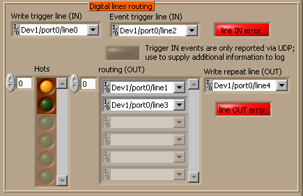
3.1.9.3 Digital routing
This tab determines how triggers are read from hardware inputs and how logical conditions are dispatched to digital outputs. The scheme works as long as one or more National Instruments DAQ cards with digital input/output ports are connected to the system. The feature is important for interfacing the recording system with external electronic hardware. It has to be kept in mind that the generation and the polling of digital signals in Gonzales is done entirely in software, and hence not absolutely reliable for timing. The jitter observed, though, seem to amount to a few milliseconds.
The controls in this group are:
Write trigger line (IN)↓ the digital port which triggers
Gonzales to write a movie, when
write if trigger↓ is turned on (section
3.1.3↑). This is equivalent to keep the
Write to file↓ button
ON as long as the trigger line is in TTL state 1. The state of this line is reflected in the
write trigger led↓ among the recording controls (section
3.1.4↑).
For this and for the similar controls in this section, any suitable port from the DAQ card or cards connected to the system can be chosen; ports can be chosen from different cards, the only limitation being that the same port is not assigned to more than one function. The control is the standard NI-DAQ widget; the name of the port can be typed in in the format Device/port/line, or chosen from a browse… menu. The entry can be left blank, or point to a non-existing port if a DAQ device is not present; the feature of
Gonzales simply won’t function, without affecting the rest of the operation.
Event trigger line (IN)↓ the program also monitors a second port. Its state doesn’t affect any function of
Gonzales, except for the fact that transitions generate an UDP logging message. The purpose of the input is to allow the logging of additional hardware events, which are reported with a message which includes the name and the frame of the file currently being recorded.
trigger↓ is a led which reflects the state of
Event trigger line (IN).
line IN status↓ shows Error if there is any problem in the definition or the operation of the digital input lines—such as card not present, port already in use or duplicate definition.
Hots↓ An array of LEDs which reflects the
result↓ LEDs of the
Formulas↓ array (section
3.1.9↑). Repeated in this frame for convenience.
routing (OUT)↓ The result of each of the
Formulas defined above can be assigned to a digital line. The control allows to select them.
Write repeat line (OUT)↓ a digital output line of the DAQ card whose state reflects that of the
writing led↓ (section
3.1.4↑). The hardware signal can be used to signal that a recording started either by an user action or by a software condition has begun or ended; if the recording is triggered by
Write trigger line (IN) instead, the time lag between the changes in state of the two can be used to monitor the response time of
Gonzales.
line OUT status↓ shows Error if there is any problem in the definition or the operation of the digital output lines, analogously to
line IN status.
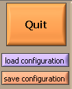
3.1.10 Session control
The correct way to terminate the program is always by clicking on the Quit button↓. Attempts to stop it differently, like by pressing on the stop button on the Labview Toolbar (an action which is left for emergency stops and troubleshooting), will most likely leave some camera resources busy, and will need quitting labview (or altogether killing the process from OS) in order to resume operation.
The program saves all the values of the controls at normal exit, and reloads them at the beginning of a new session. Configuration files can also be saved and loaded on demand, and this is what the buttons
load configuration↓ and
save configuration↓ are for, but:
NB: in the present state, attempt to load configurations saved by previous versions of the program may result in nonsensical values of one or more controls, and is better avoided.
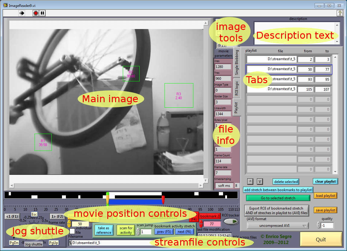
3.2 ImageReader
The program was designed as viewer for the custom streamfiles recorded by Gonzales, with options for bookmarking interesting parts of it, scanning them for visual activity, and converting entire movies or excerpts from them to AVI coded files, with lossless or lossy compression.
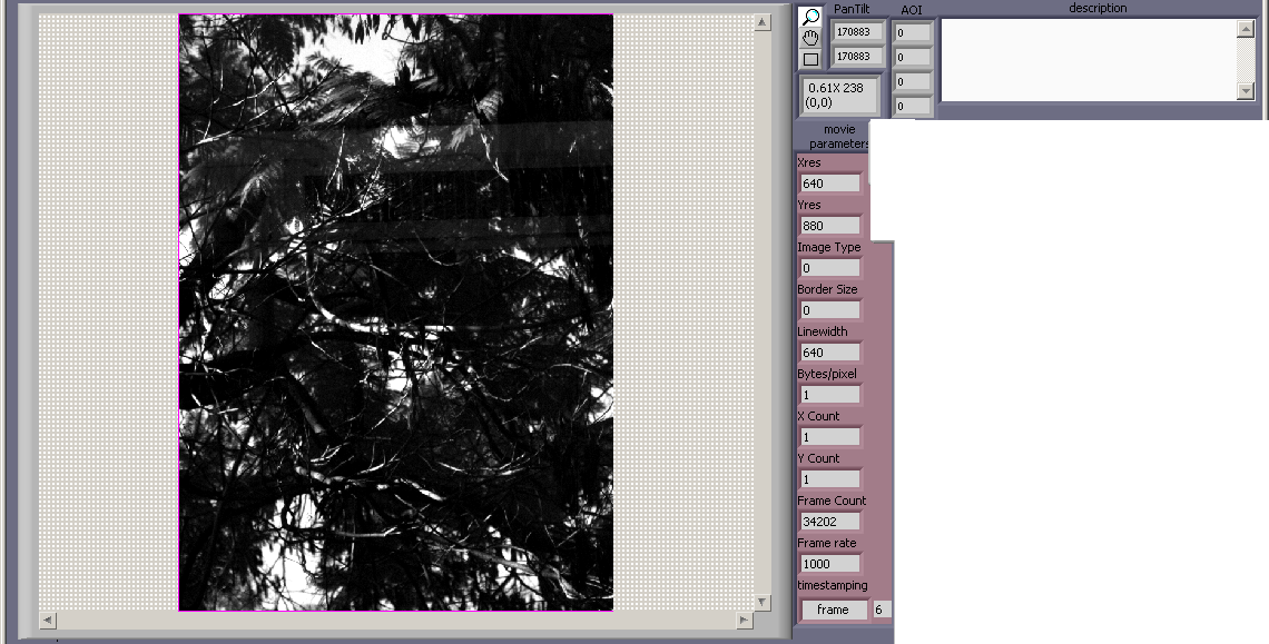
The program opens with a front panel window depicted below, where the various controls and indicators are broadly grouped according to their function.
The following paragraphs describe each group.
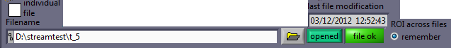
3.2.1 Streamfile controls
Operation starts when choosing which streamfile to open, by typing in
filename↓, or browsing with the folder button at its side. In principle the file can be temporarily closed, so to leave the option of access to another program, by pressing on the button
opened↓ (which changes then into
closed, press to reopen↓) at its right, though this is not too recommended (see section
3.1.3↑). The status of the opening is shown by the led on the right of the former button; it may turn to error for non-existing names, access denied (e.g. file already opened with exclusive access by another program), or disk problems.
Other controls in this group are:
last file modification↓ shows the timestamp of the last modification of the file, as reported by the OS, precise to the second. This time will be most of the time the time at which the file was closed, normally immediately after the time the last frame was recorded. It can therefore be useful to identify the chronological order of recordings, if other timestamping marking is absent. The time of last modification may be later than the time of recording only if the file is opened again for write by some program, which doesn’t happen in normal practice.
individual file/sequence files↓ When the box is checked, the reader automatically sees as concatenated files which reside in the same directory and are part of a sequence (in the sense of section
3.1.4↑, i.e. with filenames differing only by a trailing number). When playing back forward or backward, one file is played after the other; when searching files for “activity” (see below), all the files are scanned in sequence.
ROI across files↓ If on, the definition of the ROIs is remembered when closing the current file and opening a new one. If now, the ROIs are resetted.
3.2.2 Main image and File info
The main image shows the current image in the streamfile being played. It is implemented as standard Labview image widget, with features pretty the same as that of the main image in
Gonzales (see section
3.1.1↑).The image can be zoomed in/out when the
lupe↓ tool is selected, panned (
hand↓), ROIs can be drawn (
rectangle↓), and a right click menu adds a few options for handling ROIs, zooming to fit, exporting the image. Below the image tools, by the upper right corner of the image, a frame reports the current zoom factor, and the intensity value and coordinates of the pixel over which the mouse is hovering.
Other relevant indicators display information about the file.
movie parameters↓ reports all the data read from the header, as described in Appendix
A↓. The most interesting parameters for the user are Xres and Yres, the total number of frames in the movie, the frame rate and the kind of frame/timestamp.
description↓ is initially filled with the free text read from the header of the streamfile. This text can be edited, so that if excerpt of the file are saved still in streamfile format (see section
3.2.7↓), their description can be modified.
The following two indicators are displayed only if the movie was recorded with either a relevant framestamp option (see section
3.1.2↑). They will display different numbers for each frame shown. As “relevant” evolved in the course of development of the programs, and sometime the fields were used to store some diagnostic information instead of the intended one, their content may be now irrelevant.
PanTilt↓ is visible only is
software framestamp was tagged. The field was originally supposed to contain the angular coordinates pointed by the pan-tilt unit (feature dropped after Gonzales2, IIRC). Sometime later it may have been used to record some kind of frame counter for debugging purposes.
AOI↓ contains the coordinates of the image
Area
Of
Interest, if a subframe was acquired. The indicator is visible only if either the movie was recorded with the Basler camera and
camera framestamp was tagged (then the camera itself inserts the data), or
software framestamp is tagged and either camera was used (Gonzales inserts the data).
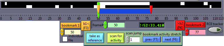
3.2.3 Movie position controls
Below the main image there is a long slider bar, labeled with numbers from 0 to the last frame. The three sliders move depending on case, and can be grabbed and positioned.
the green slider↓ points at the current frame of the movie, and moves progressively during playback. It can be dragged for immediate view of any frame within the movie. The number of the desired frame can also be entered in the numeric
frame#↓ control immediately below the bar.
the yellow slider↓ is used to bookmark the beginning of an interesting piece of the movie, and
the red slider↓ to mark its end. Both sliders can be dragged, but their position can also be changed, and be relevant in other ways.
bookmark1↓ pressed, sets the left bookmark at the current frame, i.e. brings the
yellow slider where the
green is. The left bookmark can also be set to a specific frame by entering the number in the green control below the button.
bookmark2↓ pressed, sets the right bookmark at the current frame, i.e. brings the
red slider where the
green is. The right bookmark can also be set to a specific frame by entering the number in the red control below the button.
b1<↓ shows the frame at
bookmark1, i.e. brings
the green slider to the
yellow, and continues playback from there.
>b2↓ shows the frame at
bookmark2, i.e. brings
the green slider to the
red, and continues playback from there.
The next controls have to do with how the movie can be automatically be divided in bookmarked stretches. The workings of the method are described further below in the sections
3.2.5↓,
3.2.6↓,
3.2.7↓. The buttons are described here because of their use also in browsing the movie.
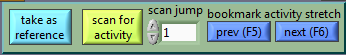
take as reference↓ stores the current images as reference, which is used as a “background” for either the blobbing tracking (section
3.2.5↓), or the ROI logic activity markup (section
3.2.6↓).
scan for activity↓ When pressed, starts a scan of the from the beginning of the current movie, continuing then to the following movies of the same sequence, if there are and if
sequence files (section
3.2.1↑) is checked. Most controls of the window are disabled during the scan, which can be canceled by pressing on a specific button which pops up while the scan is running.
scan jump↓ Since reading and processing every image of long movies can be very time consuming, while the large-scale activity scanned for can be slower, an option is provided for analyzing only one in every several images. Use 1 for maximal accuracy in locating image activity, larger numbers to save time with a coarser scan.
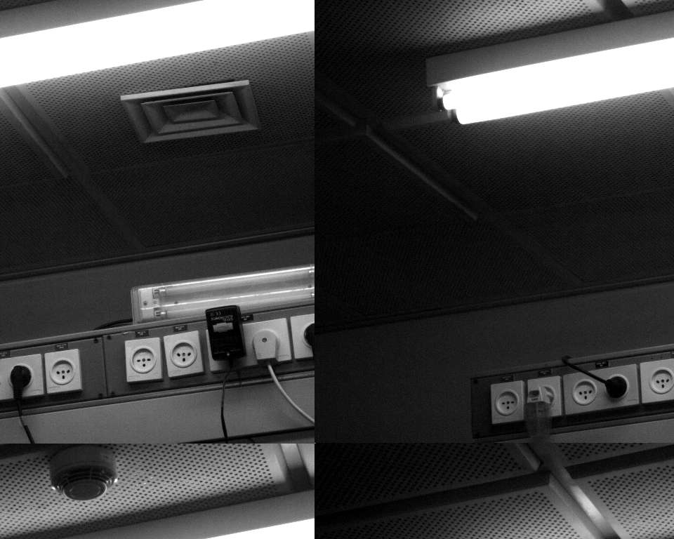
The activity bar↓ is the unnamed bar placed right below the main image frame and above the slider scale. Before any scan is done, it shows just a black uniform stripe. Once the movie is scanned, some parts of it may become white, as shown in the figure. Those parts denote stretches of the movie in which “activity” was detected. If “single blobbing” was used there will be only one line of activity marks; with “ROI logic” there will be as many lines as
Formulas used; each line corresponds to one formula from bottom up.
The activity bar stores only information for the current movie.
previous bookmark activity stretch↓ after the movie has been scanned and there is some activity content, this button moves the bookmarks (
yellow and
red slider) to the beginning and end of the previous stretch marked; moreover it sets the current frame (
green slider) at the beginning of the stretch if the movie is playing forward, at its end if playing backwards (really? wow! Better to check it).
next bookmark activity stretch↓ analogously to the previous button, moves the pointers to the following activity stretch.
ROItracker↓ is described here but belongs elsewhere. If on, the (single) ROI on the image will move around following the centroid of the tracked blob (section
3.2.5↓),.
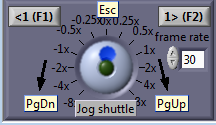
3.2.4 Jog shuttle
This composite control controls the playback speed of the movie, which can be played forward as well as backwards. At 1x, the movie will be played at the frame rate specified by
frame rate↓ (provided that the streamfile can be read fast enough and the video card is capable of; normally files are inspected and played at a much lower speed than that they were recorded at, so that is a non-issue).
At speeds larger than ±1x, only one frame every some is shown.
To ease navigation with the keyboard, the Jog shuttle commands are bound to PgDn (decrease playback speed, i.e. also go faster backwards), PgUp (increase playback speed), Esc (freezes frame), F1 (backward one frame when in freeze motion), F2 (forward one frame).
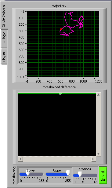
3.2.5 the Single blobbing tab
The principle of operation of “single blobbing” replicates that of “self-tracking” in Gonzales (see section
3.1.7↑). The idea, and the potential use of the feature, was that when a small object moves within the larger image, a ROI centered on the object can follow and track it. The feature has been preserved across versions of the two programs. In ImageReader, each image of the movie can be analyzed by subtracting a reference image, and the coordinates of the resulting blob can be used a) to track a sort of trajectory of the object throughout the movie, b) to dynamically move the (
only one) ROI in the frame, keeping its size and centering it on the object tracked. The dynamical ROI can be used to export a smaller movie (see section
3.2.7↓). The controls on this panel are the following:
thresholded difference↓ is a binary image showing the result of the image processing done to locate the centroid of the blob, that is a morphological erosion of the thresholded absolute difference between the image analyzed and the reference background. The Blob
↓ (sorry, I really can’t resist; see
http://en.wikipedia.org/wiki/The_Blob) is the set of points showing in white. Note that this image is updated infrequently during scanning, to save CPU time spent in screen rendering.
The widget is locked in ROI draw mode (equivalent to choose the
rectangle tool in the main image), so that rectangular ROIs can be dragged around interesting blobs.
thresholding: lower, upper, erosions↓ parallel the same controls in Gonzales, described in section
3.1.7↑.
roi>big↓ copies the position of the ROI on the thresholded difference image to the main image. For some reason I must have found this button very practical here.
trajectory↓ is an x-y graph of the position of the centroid of the detected object throughout the scanned images (one every
scan jump↓, see section
3.2.3↑) of the current movie. The trajectory is visible only if the movie has been scanned, and doesn’t retain positions of other movies in the same sequence, if there are. A red dot on the trajectory shows the centroid on the image closest to the current one.
3.2.6 the ROI logic tab
The Formula logic and use parallels that implemented in
Gonzales; it has been described extensively in section
3.1.9↑ and won’t be repeated here.
When playing and navigating a movie, the result of the boolean logic is displayed in the
Formulas↓ cluster for every current image. Moreover, the ROI logic can be exploited for scanning for activity, and hence the following controls are peculiar of
ImageReader and absent in
Gonzales:
formula to playlist↓ selects which among the
Formulas defined above is used during scanning in order to select stretches which are automatically inserted into the
playlist↓ (section
3.2.7↓). For the current movie
only, if the movie has been scanned for activity, selecting the one or the other formula will change the behavior of the
previous bookmark activity stretch↓,
next bookmark activity stretch↓ controls (section
3.2.3↑) based on the one or the other line of the previously filled
activity bar↓, that is according to the one or the other formulas, if they haven’t been changed in the meantime. When scanning a sequence of movies, unfortunately in the present implementation it is not possible to change the playlist content based on another formula without rescanning the sequence again.
dt from start↓ The stretch marked during an activity scan is contracted, retarding its beginning if
dt > 0, or extended, anticipating it if
dt < 0, with respect to the frame in which the formula changes value from
false to
true. The same
dt applies to all formulas.
dt from end↓ Analogously for the end of the stretch, with respect to the transition
true → false.
show R values↓ toggles the display of the numeric value (of the average absolute difference with the background) inside the ROIs in the main image. Suppressing may be useful to reduce clutter.
activity type↓ determines whether scanning is done using the Single Blobbing method described in section
3.2.5↑, or the
Formulas.
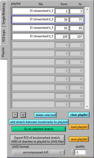
3.2.7 the Playlist tab
The playlist is a list of stretches of movies (belonging to the same or to different files, even in different directories), which can be used for quick navigation, and as a batch list for format conversion.
The entries in the playlist can be inserted in either of two ways:
-
pressing add stretch between bookmarks to playlist appends the stretch currently selected (section 3.2.3↑) to the list;
-
running a scan for activity, all the stretches identified are automatically appended to the existing playlist. If the scan spans several files of a sequence, all the relevant stretches are inserted as they are found.
The entire playlist can be deleted with the clear playlist button; it can be saved to a file or reloaded with the save playlist and load playlist buttons respectively.
An individual element of the playlist can be selected by clicking onto, and the selection is marked by a blue frame. The selection can be moved upward or downward of one element by clicking on ^ or v. Pressing the green button Go to selected stretch the current entry becomes current, i.e. the relevant file is opened, the bookmarks and the movie position are adjusted accordingly. The selected entry can also be removed from the list with the button delete selected.
The entire list of stretches present in the playlist can be exported to other files when the button Export all bookmarked stretches… is pressed. Since for exporting each single frame of each stretch has to be read, converted and written, the operation can take a lot of time and can be canceled. Formats for exporting are the original streamfile format (in which case the export is useful to save only interesting parts of the movies, or regions of interest within the image), or AVI (often useful for presentation or as input for subsequent processing software). AVI is just a general format class; images can be coded or compressed with a variety of algorithms, leading to different degrees of size saving, image quality and processing time when saving rather than when reading back the movie. For quantitative image processing, it is strongly recommended to export movies using either a lossless image codec or no compression at all. The parameter quality affects the compression codecs which are lossy; its actual meaning depends on the particular codec.
Remember that if at least a ROI is defined in the image, the movie exported includes only the part of the image within the first ROI; if no ROI is defined, or if the ROI encloses the whole image, all the content is exported. if
ROItracker↓ is on, the ROI position is adjusted per each frame according to the centroid of the blob resulting from the blobbing analysis, with the parameters currently in effect in the single blobbing tab (section
3.2.5↑).
At this moment, there is no provision in
ImageReader for reading AVI files. The utility
AVItoStreamfile described below (section
3.3.3↓) can be used to convert back.
3.3 Goodies
3.3.1 WriteSpeedTestNormal
A minimal labview tool to check the sustained write throughput of the RAID array. It writes where it finds free. The main point in using it is that it is written in Labview, hence in principle it should be subjected to the same eventual limitations in performance that Gonzales is subjected to.
The program simply tries to write repeatedly a chunk block of arbitrary data to File to write, relying on the OS for determining how this data has to be written on the surface of the disk. The amount of bytes written, per second and since the start of the run, are monitored. The average write throughput is affected by the write policy options with which the RAID disk array has been configured, by the position on the disk and contiguity of the data written, by the frequency of write operations to the disk and the size of the unit block written, and by low-level OS options about the write, such as Unbuffered! write or direct call of the OS file functions.
The controls on this UI are supposed to be self-explanatory for the user needing to use this tool, and aren’t described in detail here. The desired values have to be set before the program is run.
WriteSpeedTestNormal can also be run in parallel with Gonzales (only grabbing, not saving) or one of the Bitflow grabbing examples, like MultiBufferGrab.vi, in order to assess whether simultaneous grabbing affects the writing performance (it should to some extent, as both compete for memory and bus bandwidth).
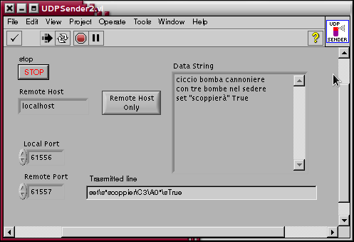
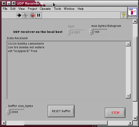
3.3.2 UDPSender2 and UDPReceiver2
Two basic VIs for testing UDP communication with Gonzales and BEst. The first one sends arbitrary strings to a specified UDP port; strings are sent out when they are terminated by a newline. The second one listens on the specified UDP port for incoming data. There is also an UDPReceiver2, which was developed to test the feature of setting arbitrary controls via UDP commands set “control” value.
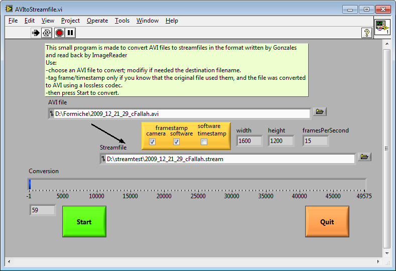
3.3.3 AVItoStreamfile
Since
ImageReader was not designed to read but files in the custom format described in Appendix
A↓, while for testing purposes it may be useful to inspect other movies, a tiny tool for format conversion of one movie at a time has been provided. Of course conversion takes additional time and requires disk space which would both be saved if
ImageReader could read AVI files directly. From the development point of view, though, it was way easier to produce a tiny helper tool, which is anticipated to be used infrequently, rather than to augment
ImageReader with the read AVI capability.
The controls here should really be self-explanatory, and anyway short instructions are provided onscreen in the yellow frame.
3.3.4 matlab scripts
movietimestamp2.m gives an example of reading the whole array of framestamps (if present) and timestamps of a movie, and of accessing an individual image. Having the whole frame and timestamps at once in arrays allows easy computations and checks of recording timing jitter.
A Streamfile API
Streamfiles format since Gonzales3
Blocks in the file are padded to the next multiple of the sector size, for streaming efficiency. The sector size of the RAID array of the development system was 512 bytes, as well as of many other hard disks. In fact, I don’t think I considered the problem of porting streamfiles across hard disks with different sector sizes - that is, the programs may misalign the contents if the sector size happens to differ, or the reader may not be able to read streamfiles copied onto a disk with different size partitioning. Anyway.
Content is as follow:
Header (first block, size=1 sector):
xres (U32)
yres (U32)
ImageType (U32)
BorderSize (U32) (in Labview, images have Borders; extra allocation helps image processing). For us, always 0.
Linewidth (pixels) (U32) (>= xres, IIUC =xres+2*bordersize)
Bytes per pixel (U32). 1 in all our takes.
Xcount (U32) number of images mosaiced in one write, for us always 1.
Ycount (U32) idem
TotalFrameCount (U32)
FrameRate (U32) (approximated to integer)
EmbeddedTimestampMode (U32):
-
bit 0 → Basler Stamp (inserted by the camera at source): AOI (4*U16) and image counter (U16) in the last 10 pixels of the last image line.
-
bit 1 → Software timestamp (inserted by Gonzales): the first 20 pixels of the last line contain: image counter (U32), AOI (4*U16), Pan Tilt (2*I32). Versions of Gonzales later than 3 may have written other test and statistic data (e.g. grabbed buffed number) in place of the no more present PTU coordinates; do not relate to them.
-
bit 2 → Optronis timestamp (inserted by the camera at source): the first 2 pixels of the first line should contain image counter (U16) [the buggy firmware of the older Optronis writes garbage here, the other cameras are ok]
-
bit 3 → Software millisecond absolute timestamp (inserted by Gonzales, subjected to OS jitter): (U64) counter representing the number of milliseconds from 1/1/1904, written in place of first 8 pixels of the first line, i.e. the upper left corner. (Was not implemented, hence bit3==0, until Gonzales8).
Description (char*458, \0 terminated): free text
Each image contains:
yres*linewidth*bytesperpixel bytes, stored consecutively (no idea if line-major or column major)
Images always start at the beginning of a sector. Hence, image N begins in the file at byte sector_size*(1+N*ceil(yres*linewidth*bytesperpixel/sector_size)).
In images with an embedded timestamp, some pixel values of the first or last line are replaced by the numeric values of the data specified above.
B Changelogs
For historical memory.
Gatto10
26/10/2014
ImageReader 9.3
-
hotfix: img_read_file_Normal receives also the argument LineWidth, because apparently the alignment requirement has changed from multiple of 32 bytes to multiples of 64 bytes somewhen across time. Old streamfiles, especially ROI cuts with odd horizontal sizes, recorded in the past, have values of LineWidth recorded in the header which don’t match anymore what IMAQ GetImagePixelPtr reports for an image buffer of the same exact size, hence the stored value of LineWidth has to be taken into account instead.
12/3/2014
Gonzales 10.3
(from 10.2, wasn’t able to backconvert 10.2.1):
-
in Self Track. the center of the ROI can be moved not just to the center of the detected blob, but also at any of the eight corner and mid-side positions of the bounding rectangle. This is done to help automatic positioning of optical threshold detectors with moving poles.
-
"lower threshold", "upper threshold" and "erosions" unbundled in order to be directly controllable by UDP set commands.
-
In principle, numeric arrays too can set via UDP commands. That was done for changing "ROI size", but the periodic check to rebound the ROI inside the frame renders that ineffective as of now.
-
minor glitches addressed, strings of "formula to Write to file" updated on start, and "load configuration", "save configuration" forced to false
2/1/2014
System #4 for Noy.
Gonzales 10.2.1:
-
Just recompile for LV2013_64bit, moved to .2 to safeguard from possible changes. In fact, enlargement of the ringbuffer to 600 images (more than that seems to impact negatively performance and to cause stability problems); possibly other minor FP size adjustments.
ImageReader 9.2:
-
timestamp as string appended into the AVI frame data when stream is exported to AVI. No check on source is done, i.e. when exporting to AVI streamfiles which have not been recorded with "software timestamp" tagged, garbage will be present in that position
(I’ve found on backup disk a 9.1 dated 16/1/2013; that was probably just a test, but to be on the safe side and avoid confusion I advanced to 9.2)
AVIfileLister:
-
quick snippet to read the timestamps of the first and last frame of all AVI files in a selected directory (supposed exported by ImageReader9.2 from a streamfile recorded with "software timestamp" tagged), and to dump the information into a csv file.
Gatto9
15/8/2013
Gonzales 10.2:
-
solve bug "UDP in error" not clearing unless restarting the big loop
-
solve bug frame in movie repoted as #0 when udp reporting activity of hotspot>1. Hopefully not broken the frame# reporting upon trigger, because the fix was about a mixup there.
FIXME: when the file mode is not progressive, i.e. when writing to file is stopped and resumed again, the report about writing and triggers refers to a frame number which is resetted to 0 at each resume, and hence wrong.
TODO: The frame number is reported if "writing" is on. That is, it is reported as 0, trivially, when writing starts (save the bug above) and not reported when it stops. Improve the logic so that the frame number is reported either when "writing" is on, or when changed from on to off, or when changed to on and file mode is not progressive.
19/3/2013
Gonzales 10.1:
-
add a "Not Write repeat line (OUT)" for Tess
21/1/2013
ImageReader9.1:
-
subvis for Load/Save ROI logic. No visible FP change if excluding perhaps very minor cosmetics.
Gonzales10:
-
ROI logic instead of Hotspots; triggers & hotspots tab reorganized.
-
automatism to choose the Karbon SDK path and Karbon card registry entry on the system, hopefully allowing same code to work on all systems.
-
UDP listener to generate arbitrary control changes events (first use thought: new background, also commanded write start)
-
Chosen ROI formula triggers Write start OR Write in effect (selectable)
-
reconfiguration of DI/O and UDP ports does not restart grabbing, as did before due to lazy programming.
15/1/2013
ImageReader9:
Glitches corrected:
-
no ROI on opening the program;
-
default "remember ROI across files"
-
ROI diff average values updated also when pressing "take as ref"
1/1/2013
ImageReader9rc:
-
ROI logic for scanning activity: new tab with boolean formulas, choice between old mode "blobbing" activity and new logic mode; definition of stretched with start and end anticipated/retarded with respect to the activity detected on image; annotation of the main image with ROI name and mean absolute difference value; saving and loading of ROI definitions and formulas.
-
some code modularization in the scanXact event frame, to allow development.
-
image updates while scanning for activity.
-
minor cosmetic FP and wiring cleanup.
-
TODO: double buffering and simultaneous read/process could speed up scanning and export?
Gatto8+
25/12/2012
Gonzales 9.3
Testing on the new system under 64bit OS, LV2012, SDK5.60.
-
path and registry key for the new environment (to be hardwired on the BD according to case)
-
avoided unnecessary registry writes if camera configuration is not changed.
-
avoided restarting grabbing when pixel clock or #taps is changed. Avoids a frequent loss of sync of the frame after the very first few images grabbed, while settings are changed.
-
added a boolean indicator "setting camera". Main use, to flag the completion of the serial settings, to reference the first fiducial framestamp. The count of "lost frames" (when camera framestamp is checked) is now correct.
-
All stream file access functions use now normal (unbuffered) file access functions, avoiding the original direct calls to kernel32.dll. Same functionality, hopefully more portability.
-
changed ROI save in configuration file, still not satisfactory (restores as ROI the global rectangle, not all ROIs).
-
write configuration on exit copes nicely with configuration file not previously existing.
-
minor cosmetic changes (wire positions) on the BD. Many blocks wrapped by conditional disables for testing, left in place.
-
observed occasional MemoryManager.cpp crashes. To be cleared whether LV bug or race condition.
-
Observed higher tendency of locking the frame out of sync, notably immediately after changing to a new frame mode. An operative workaround, if the image locks out of sync, is to select again the same "Karbon camera configuration" from pull down menu, and repeat if necessary. If it doesn’t help, usually lowering the fps, selecting the configuration, and increasing fps afterwards does the trick.
TODO: make nicer icons.
SDK5.60
23/12/2012
Gonzales 9.2
transitional backup version
27/9/2012
Gonzales 9.1
-
Message reporting logic changed attempting to achieve more reliable frame# report. Local interthread variables store the grabbed frame number at the time the last trigger/hotspot was received, and the reporting thread which builds the message reads these variables, even if running asynchronously.
-
autosaved configuration file now called <VI_name>Config.dat instead of GrabberConfig.dat to avoid mixup of files when running variation VIs from the same directory.
-
ROI position saved across sessions.
-
attempting to get a correct count of "lost frames", but still not finding the logic mistake.
11/7/2012
Gonzales9
-
best attempt to achieve a millisecond precision software timestamp. The timestamp is obtained by combining the system clock and the BIOS ticker. Both have millisecond resolution, but the former is updated at a rate decided by the OS (every ~15ms on windows XP, every ~1ms on linux and windows7). The timer readouts achieved seem accurate to +-1ms as long as the screen activity is minimal. Plotting a new image in the main Gonzales window adds delays of ~5-10ms, and displaying Gonzales statistics even of ~50ms.
-
a new option for soft stamping the streamed images with this timestamp is implemented. The timestamp consists of 8 bytes written in place of the upper left corner, representing the number of milliseconds from 1/1/1904. Images can be marked with this timestamp as well as with the camera hard framestamp and soft framestamp previously implemented, so that their mutual consistency can be further checked. The considerations about the jitter and reliability of this software timestamp apply.
-
one further digital input line is polled, so to provide the option of marking an additional trigger event (additional to the trigger used to start the recording).
-
UDP reporting of various events, including start/stop of writing, file closing/reopening, hotspot activity, external hardware triggering. The report datagram includes the presumed timestamp, the kind of event, the current filename and the estimated frame number simultaneous with the event. The pretrigger offset is for the moment NOT taken into account in the computation of the frame, while the queue backlog is. The above considerations about the accuracy and jitter of the software timestamp apply. The UDP reporting can be directed to any single host (named or IP address) and port. It could be easily changed to broadcasting. The current design allows for a maximum of 100 report datagrams per second, but that is not a hard limit.
-
the logic of polling the digital input lines and repeating on digital outputs has been somewhat changed, and it would be better to recheck that they function correctly.
ImageReader8
-
support for the new software timestamping mode.
Miscellaneous:
A matlab function, movietimestamp2(), is provided for extracting hard (Optronis only) and soft framestamps, as well as soft framestamps from a streamed movie. It is also a good example of reading the streamfiles according to the previously communicated API.
Usage example: to check that no frame is lost, and the accuracy of the software timestamping:
[t_movie,s_framestamp,c_framestamp,img1]=movietimestamp2(’F:\testGonzales9\r’);
subplot(311),plot(diff(t_movie));
subplot(312),plot(diff(s_framestamp));
subplot(313),plot(diff(c_framestamp));
A minimal UDP listener implemented in Labview is also provided, for debugging. The listener is directed to the configured port of localhost.
Gatto6&7
21/9/2011
New features in ImageReader5:
-
improved navigation of sequenced files. A sequence is here defined as a set of streaming files, residing in the same directory, and having filenames differing only by a _NNNN ending, where NNNN is any integer number (no limitation about number of figures, nor is needed for numbers to be consecutive, as intermediate files may have been removed). An eventual file sharing the same name, but without the _NNNN ending is considered the first one of the sequence.
-
A new checkbox by the jog-shuttle control determines whether the reader works in single file mode or sequence mode.
In sequence mode:
-
play forward/backward automatically moves to the next/previous file of the sequence;
-
in paused mode, single stepping is also through files of the sequence.
-
Search for activity continues from the current file on, to the last file of the sequence, using the same reference image initially chosen. Activity (i.e., frames sufficiently different than the reference) stretches are automatically inserted in the playlist.
-
Playlist.
A new list of stream stretches can be used. Each entry of this list contains the filename reference to the movie, a start and an end point. Filenames can belong to different sequences and reside in different directories. Filenames cannot be edited, but start and end frame number can. An unlimited number of stretches, even overlapping, of the same movie can be inserted in the playlist. The playlist is not for "playing" the stretches in sequence, but is intended to be a repository of bookmarks into different files at once, and a list of stretches to be exported in batch, unsupervised operation. Entries in the playlist can be inserted or removed manually, copying the current filename and bookmark position, or automatically, as the result of a scan for activity search. The playlist can be saved to file and retrieved; it can be navigated. No provision is made for reordering it, though. The reader can be made to play the currently selected entry of the playlist at a click. [No, I don’t know how to make more evident the highlight of the selected entry]. An export action exports FIRST the stretch of the current movie between bookmarks (previous behavior), THEN continues exporting one after the other the entries of the playlist FOLLOWING the currently selected one. This is not the most ergonomic behaviour, and could be improved in future. The usage scenario for the time being would be to select in the playlist the first stretch to be exported (could be at any point of the playlist), render it current, and then start the exporting. Exporting and scanning for activity can be canceled at any time even when they navigate through multiple files [but there seems to be a bug as sometimes the cancel button does not react — to be investigated]
-
Search for activity: if(?) no ROI is selected in the main image (right mouse button/clear ROI), then the ROI resulting after the search will be the largest rectangle containing all the "active" pixels across all images scanned and tested. This feature allows to preselect automatically an "interesting" subregion of the image. The resulting ROI will just contain the active pixels; an eventual guard border has to be added manually a posteriori by enlarging the ROI found.
-
improved robustness of the program when reading corrupted files (but no attempt made yet to guess the correct movie parameters of stream files with missing or corrupted header block). [Corrupted headers also usually result in an abnormally large number of frames; I still have to prevent the program from trying to loop on the nonexistent frames when playing in sequence, or scanning for activity, otherwise the program does it forever].
-
Timestamping:
As of now, the following sources of framestamping and timestamping are available:
-
the OS marks the creation date, the closing date and the last access date of the file to the precision of 1 sec. Currently ImageReader5 reports the second of these three, which is the one most easily achievable with LV. These already provide an identifier.
-
at recording time, the user can presently choose to activate camera timestamping and soft timestamping. The former, for the camera with the correct firmware release, is a 16 bit counter, which advances at every frame, i.e. regardless of whether we are writing to file or not. The information is stored in corner pixels of the image. The soft framestamp also writes to corner pixels the values of two I32 program counters, which are also running since the program is started. Non identity of these two values already implies some loss. All these counters can be used to some extent to determine the timing of each frame and to detect frame losses. For instance, the values of each of these counters have to increment by 1 at each frame; larger increments mean either a frame loss or an interrupted and resumed recording [which is one of the currently possible modes of operation!]. Jumps forward of these counter of as many frames as the ringbuffer size (currently 400), or multiples of, denote a buffer full condition, i.e. a sustained slowing down of the write-to-disk thread w.r.o. the grabbing thread. The framestamp provided by the camera is absolutely (in the sense, not affected by software jitter) reliable, but wraps around 2^16, that is every 65sec at 1000fps. Hence it provides only timing information modulo that amount. Relative timing of a frame within a movie is currently calculated by multiplying the counter increment since the first frame of the movie by the movie fps. The only "absolute" timing achievable as of now, considers the absolute value of these counters, which is at best relative to the time either the camera was turned on or the grabbing program was started, i.e. not too useful.
An implementation of absolute (PC clock) soft timestamping of the grabbing time of each frame is under consideration.
It seems that Scan For Activity, when launched in sequence mode, can be canceled anytime during the scan of the first movie, but only at the end of the subsequent ones (problem of front panel reactivity probably due to the chaining of event cases enforce to achieve the sequenced scan).
New features in Gonzales7:
In course of evaluation, probably will be implemented in the near future:
-
Absolute soft timestamping of the frame in corner pixels, as double precision second counter since 1/1/1904. Would either replace and supersede the previous PTU position stamp, currently used as grab loop/write loop counter stamp (2xI32), or augment it, perhaps classifying it as a new stamping option (file header, etc). That would represent the time of arrival of the frame from framegrabber to memory; not the absolute shooting time, but valuable for referencing and studying the grabbing jitter.
Miscellaneous comments about the systems:
-
The present design pattern of the recording system is the only possible one which allows pretriggered recording of the images with the given hardware, for unpredictable trigger occurrence. That is, given that neither the camera or the framegrabber have image memory, we run the camera continuously, store a heap of recent images within the computer memory, and if a trigger appears we decide which images to transfer to disk.
Our program, written in user space on a GUI-reactive system, has to stand behind the two time-critical tasks - download images from the framegrabber before it is too late, and poll a trigger input - and take software decisions.
If we would always be in the conditions where the trigger occurrence could be anticipated (e.g., if the control of the trigger event would be our call, not if the trigger depends on the occurrence of some external and unpredictable event), then we could switch to a model in which the camera is "turned on" and starts to deliver frames only with the selected anticipation before the trigger. That design would allow the trigger to be taken care by non-user-interaction dependent hardware, which could enforce real strict timing. For instance, a pulse generator (card, eventually) providing the camera frame sync, which would start its train of pulses at the activation of a pretrigger input, which would precede the trigger output by a preprogrammed time. Our program design would have however to be significantly revised.
The path I have been pursuing so far, instead, has been of trying to identify all existing impediments to the time critical tasks, and to decouple them, in order to maintain the existing GUI driven, user space design pattern, which is more comfortable for me to work with.
-
It is recommendable to upgrade Udi’s system with some sort of graphic card. It seems that screen drawing operations take always a high system priority, which heavily interferes with other time critical tasks. On Udi’s system these are noticeably slower and heavier to the system than on Inbar’s system.
Though programmatically it is possible (and has been largely done so far) to limit heavily the amount of redraw operations, it is not desirable to have none of them. It seems (but see next point) that the producer-consumer thread model for grabbing and writing to disk is still able to cope with the maximal target bandwidth without loss of frames, but high jitter is then apparent, as evidenced for instance by fluctuations of the loop repetition rate and ringbuffer fill. This jitter is almost absent in Inbar’s system. Moreover Inbar’s system is even as of now way more repeatable w.r.o. trigger timing repeatability when the trigger is polled from the USB DAQ card. That this is due to a competition of priorities is merely an educated guess so far.
-
The camera used in Udi’s setup has an older version of its firmware, which is incapable of writing correct framestamps. Upgrade is recommended in order to be able to monitor the performance and the eventual loss of frames of the recording system, which presently is only indirectly possible and not always conclusive.
-
Udi’s system seems slightly unstable, but precise causes and cures unassessed. Unknown whether eventual BIOS or framegrabber firmware upgrades might help. Recurring complaints are inability to cold boot if an USB peripheric is connected, and rare nonrecognition of the framegrabber card at cold boot, usually solved by turning off the system for a while, in extreme cases by removing and reinserting the framegrabber card.
-
To be assessed if the use of a PCI DI/O card (rather than the present USB DAQ) could provide stricter overall reaction times to the recording trigger, which is currently software polled.
Gatto 5
21/1/2011
Gonzales5 & 6
ImageReader4
Gatto4
21/9/2010
Gonzales4
-
writing to windows registry for configurations
-
removed range camera, camera-PTU registration and PTU drive
ImageReader4
Gatto 3
6/1/2010
ImageReader4 18/1/2010
Gatto 2
23/11/2009
Gonzales3
Still had the option of integrated tracking with a range camera, and PID control of a pan-tilt head for the fast camera. The option was later abandoned because of poor performance and stability of the setup.
19/11/2009
Gonzales2
17/11/2009
Gonzales
Incorporated TopoTracker, not yet self-tracking. Optronis already in use, but only fps change implemented.
TopoTracker
An original IMAQdx camera+PTU application then merged into Gonzales
FastCameraStream11-13
23/11/2009
ImageReader3
ImageReader2
Gatto
Most of the contents of the directory have to do with frustrating attempts to benchmark disk streaming.
FastCameraStream
The very first attempts of Gonzales were called FastCameraStream, FastCameraStream2-11, for the record.
12/10/2009
ImageReader2
The latter had already in nuce the ideas and look of the current one.
11/10/2009
ImageReader
C Problems encountered in the past
-
Framegrabber not seen in system #2.1.1↑, see 2.1.3↑. Symptom: Gonzales opens without responding and after a while trows obscure errors about Bitflow routines. To troubleshoot: open the Bitflow utilities PCIwalk: if no framegrabber is listed there, we have the problem. Other Bitflow utilities will also fail throwing errors.
-
RAID disk failures, see 2.1.4↑.
-
Losses of sync, see 3.1.1↑.
-
Salt and pepper noise, see 3.1.2↑.
-
Basler degradation of the image: it was some image degradation, or loss of sync, or NI framegrabber timeout after some minutes of work of the camera (don’t exactly remember). What I do remember is that me and Udi went crazy in searching the cause, trying to correlate it to cables, temperature, time of the day. At the end it turned out that the original power supply of the camera was faulty, and replacement with an off-the-shelf switching PS bought at Tzafrir solved the problem.
Index
>b2: ↑
AOI: ↑
Acquired frame: ↑
Allow: ↑
Digital lines routing: ↑
Event trigger line (IN): ↑
Formula to Write to file: ↑
Formulas: ↑, ↑, ↑
Formulas (Gonzales): ↑
Frame position: ↑
Global Rectangle: ↑
Host reported to: ↑
Hots: ↑
Hotspot: ↑, ↑
Hotspots: ↑
Karbon camera configuration: ↑, ↑
Load ROI logic (Gonzales): ↑
Local in port: ↑, ↑
Local out port: ↑
Lower threshold (Gonzales): ↑
PanTilt: ↑
Quit button: ↑
R value: ↑
ROI: ↑
ROI across files: ↑
ROI all: ↑
ROI size: ↑
ROI write: ↑
ROI x offset: ↑
ROI y offset: ↑
ROItracker: ↑, ↑
Remote in port: ↑
Save ROI logic (Gonzales): ↑
Show Image: ↑
The Blob: ↑
The activity bar: ↑, ↑
UDP in status: ↑
UDP out status: ↑
UDP remote commanding: ↑
UDP reporting: ↑
Upper threshold (Gonzales): ↑
Visible stat: ↑
Write repeat line (OUT): ↑
Write to file: ↑, ↑, ↑
Write trigger line (IN): ↑
activity type: ↑
auto update ref: ↑
b1<: ↑
backlog: ↑
bookmark1: ↑
bookmark2: ↑
camera framestamp: ↑
camera setup: ↑
camera setup status: ↑
closed, press to reopen (Image Reader): ↑
command accepted: ↑
command line: ↑
crosshair: ↑
datagram: ↑
description (ImageReader): ↑
description text (Gonzales): ↑
dt from end: ↑
dt from start: ↑
dt histogram: ↑
erosions (Gonzales): ↑
event trigger led: ↑
every (Gonzales): ↑
exposure time us: ↑
exposure time us, exp max: ↑
filename (ImageReader): ↑
first frame in movie: ↑
formula label: ↑
formula result: ↑, ↑
formula syntax: ↑
formula to playlist: ↑
fps: ↑
fps max: ↑
frame number (ImageReader): ↑
frame rate (Jog shuttle): ↑
grab fps: ↑
hand: ↑, ↑
hotspot extraction time: ↑
images written: ↑
individual file/sequence files: ↑
last file modification: ↑
line IN status: ↑
line OUT status: ↑
load configuration: ↑
loss log: ↑
lost frames: ↑
lupe: ↑, ↑
movie parameters: ↑
next bookmark activity stretch: ↑, ↑
number of images in queue: ↑
number of images to record: ↑, ↑
open file button (Gonzales): ↑
opened (Image Reader): ↑
optical Write to file mode: ↑
pixel clock: ↑
playlist: ↑
pretrigger time: ↑
previous bookmark activity stretch: ↑, ↑
progressive files: ↑, ↑
queue log: ↑
rectangle: ↑, ↑
reference background image (Gonzales): ↑, ↑
reference image (Gonzales): ↑
roi>big: ↑
routing (OUT): ↑
save configuration: ↑
scan for activity: ↑
scan jump: ↑, ↑
self tracking: ↑, ↑
selftracking delay: ↑
setting led: ↑
show R values: ↑
software framestamp: ↑
software timestamp: ↑
streamfile (Gonzales): ↑, ↑
take as reference: ↑
take as reference (ImageReader): ↑
taps: ↑
the green slider: ↑
the red slider: ↑
the yellow slider: ↑
thresholded difference (ImageReader): ↑
thresholded self: ↑
thresholding: lower, upper, erosions (ImageReader): ↑
time loss percent: ↑
time recorded: ↑
total recording time: ↑
trajectory: ↑
trigger check interval: ↑
write if present in self: ↑
write if trigger: ↑, ↑
write loop fps: ↑
write trigger led: ↑
writing led: ↑, ↑